Concealed-Grid Ceiling System
UET’s Concealed-Grid Ceiling System is designed for ceiling layouts where the supporting frame is coordinated behind the facing panels. The system uses main channels, conceal cross tees, hangers, perimeter channels, and facing elements. Confirm the selected panel, module, edge detail, suspension condition, and project drawings before specification or ordering.
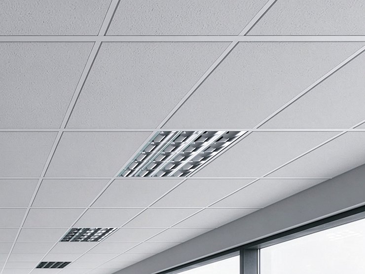
Concealed-Grid System Components
| Component | Handbook-listed section or detail | Coordination note |
| Main Channel | CB 38 × 12 | Confirm the section, length, connection detail, and suspension arrangement for the selected layout. |
| Conceal Cross Tee | TB 32 × 15 | Confirm the connection with the main channel and the selected panel or facing arrangement. |
| Conceal Cross Tee | TB 10 × 10 | Confirm the applicable grid position and compatibility with the project module. |
| Conceal Cross Tee | TB 20 × 20 | Confirm the applicable grid position and compatibility with the project module. |
| Hanger | TB 38-2 | Confirm suspension spacing, structural support, and the required connection detail. |
| W Perimeter Channel | Perimeter support and edge interface | Confirm perimeter dimensions, wall conditions, and the visible edge treatment. |
| Facing Panel | Visible ceiling surface | Confirm panel dimensions, edge detail, thickness, weight, and access requirements. |
| Coordinated element | Integrated lighting element | Coordinate the light opening, support, service access, and visible finish with the ceiling layout. |
How the Concealed-Grid System Works
A concealed-grid ceiling places the supporting frame behind the visible facing elements, so the panel layout and edge detail must be coordinated with the underlying channels and cross tees. The final arrangement depends on the panel dimensions, module, suspension points, perimeter conditions, lighting, service openings, and access requirements. Review the reflected ceiling plan and the applicable system drawing together before ordering.
Main Channel and Cross Tee Layout
The main channel provides the primary grid direction, while the conceal cross tees establish the panel module and support the selected facing arrangement. Confirm the CB 38 × 12 main channel and the applicable TB 32 × 15, TB 10 × 10, or TB 20 × 20 cross tee against the project section and connection detail.
Hangers and Perimeter Conditions
The hanger and perimeter channel must be coordinated with the structural support, wall conditions, ceiling level, and required perimeter finish. Confirm suspension spacing, fixing points, wall alignment, and access around the room boundary before finalizing the layout.
Facing Panels and Service Elements
The facing panel, lighting, air-conditioning outlets, inspection access, and other ceiling services should be resolved in the reflected ceiling plan. Do not assume that a standard panel module or lighting opening is compatible without checking the selected system and project drawings.
Project Applications
Concealed-grid systems can be coordinated for commercial, office, institutional, hospitality, and other interior projects that require a controlled ceiling appearance. The examples below describe coordination directions, not project-specific certifications or performance guarantees.

Commercial Spaces
Coordinate the concealed grid with modular panels, lighting, air-conditioning outlets, service access, and perimeter details in commercial interiors.
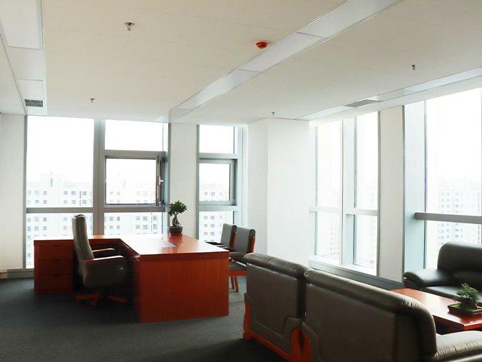
Office Spaces
Review the ceiling module, lighting layout, access requirements, and visible panel arrangement around the needs of the office interior.
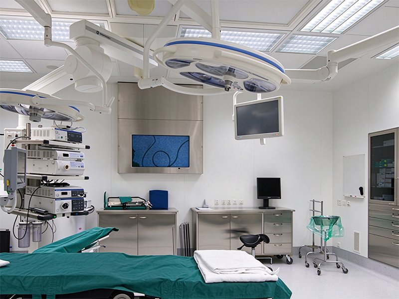
Healthcare Facilities
Confirm the selected panel, maintenance access, service coordination, perimeter conditions, and project-specific requirements before selecting the concealed arrangement.
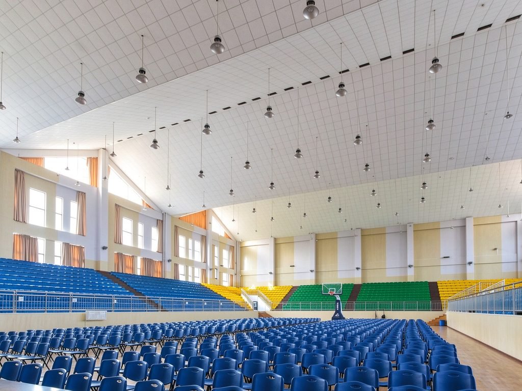
Culture, Sports & Education
Coordinate panel layout, room scale, suspension conditions, access points, and installation sequence for educational, cultural, and sports spaces.
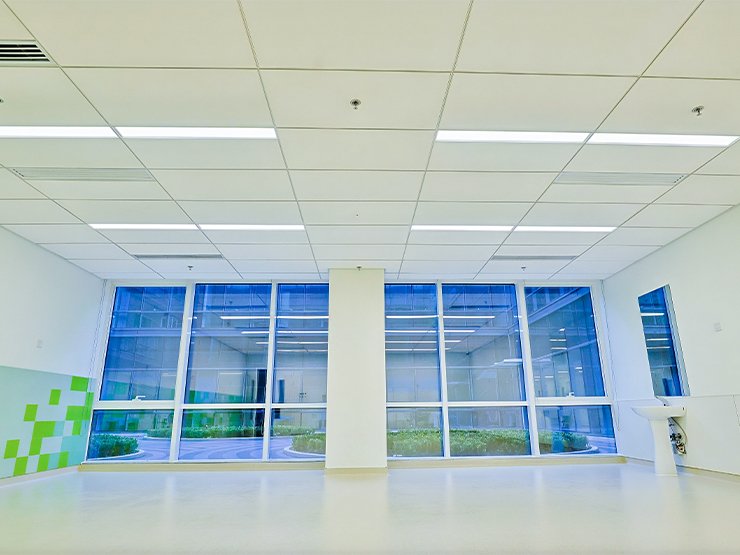
Hotels & Buildings
Coordinate the grid with room layouts, public areas, lighting, maintenance access, and the required ceiling appearance across building interiors.
Installation & Compatibility
Before specifying the Concealed-Grid Ceiling System, confirm the selected panel dimensions, thickness, weight, and edge detail. Review the main channel, conceal cross tees, hanger, perimeter channel, suspension points, service openings, and installation conditions against the project drawings and current technical documents.
- Ceiling panel dimensions, thickness, weight, and edge detail
- Required ceiling module and concealed frame layout
- Main channel, cross tee, hanger, and perimeter sections
- Suspension points and structural support
- Perimeter conditions and visible edge treatment
- Lighting, inspection panels, and service openings
- Access and maintenance requirements
Product Documents & Inquiry
For a Concealed-Grid Ceiling System inquiry, share the selected panel, panel dimensions and edge detail, required ceiling module, reflected ceiling plan or layout drawing, suspension and perimeter conditions, estimated quantity, project destination, and any lighting or service requirements. UET Ceilings can then review the suitable component set, current technical documents, compatibility, and ordering details.
Concealed-Grid System FAQ
Need a Concealed-Grid Ceiling System for Your Project?
Share your panel dimensions, edge details, ceiling layout or drawings, preferred finish, estimated quantity, and project destination. We can help review the concealed-grid arrangement, component requirements, and technical information needed for your inquiry.